Choosing the right Flanged Type Globe Valve begins with the process, not the catalogue photograph. A valve may look robust yet fail when temperature, pressure, or fluid chemistry changes. Experienced engineers examine the medium, flow direction, operating frequency, and required shutoff performance before selecting materials or trim. Small details matter. A gritty handwheel can signal poor maintenance access. A wrongly sized seat can create noise, erosion, and unstable control.
Valve engineering specialist Dr. V. C. Natarajan has expressed a useful principle: “Valve selection must begin with service conditions, not with valve appearance.” This practical view supports a disciplined evaluation of body material, pressure class, end connection, bonnet design, and actuator requirements. A Flanged Type Globe Valve should also match the pipeline’s flange standard and available installation space. Otherwise, even a technically sound valve may become difficult to fit or repair.
Real projects are rarely perfect. Flow data may be incomplete. Future operating conditions may be guessed. That uncertainty deserves attention, not concealment. Engineers should verify pressure drops, temperature limits, corrosion risks, and maintenance procedures with reliable technical documents. They should also ask whether manual operation is realistic after years of service. A heavy valve installed above shoulder height is not a convenient valve.
This guide explores practical selection decisions, common specification mistakes, and field considerations. It does not treat one design as universally correct. The best choice depends on evidence, operating experience, and honest review of what the system may demand.
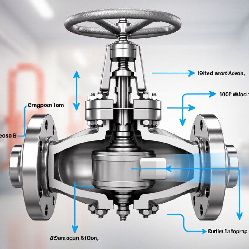
Choosing the right flanged globe valve starts with understanding its operating principle. A disc moves toward a fixed seat, controlling the fluid passage. Its body, bonnet, stem, disc, and seat form the working assembly. The stem moves linearly, unlike quarter-turn isolation valves. This design supports accurate throttling, but creates noticeable pressure loss. Think of a narrowing doorway.
Selection must match fluid type, pressure, temperature, flow rate, and maintenance access. Flange dimensions and pressure class should follow piping standards, including ASME B16.5. Check the pressure-temperature rating. Not pressure alone. For steam or hot water, review seat, packing, and body materials carefully.
The 2024 Industrial Valves Market Report by Fortune Business Insights estimated the global market near USD 79 billion. It also projected continued growth through 2032, reflecting sustained process-infrastructure investment. Market size does not prove suitability.
During operation, turning the handwheel lowers the disc toward the seat. Partial closure redirects fluid around the disc and regulates the opening. A rising stem provides visible position feedback during inspection. Before ordering, compare the required Cv with published flow data. Oversizing may appear safer, yet it can cause poor control and seat wear. A common field-review mistake is focusing only on flange size. I would also examine actuator force, shutoff expectations, installation orientation, and spare-part access. Keep it practical.
How to Choose the Right Flanged Type Globe Valve
Key Factors for Selecting the Suitable Valve Size and Rating
Choosing the right flanged globe valve starts with process data, not pipe diameter. The nominal line size provides a useful reference, but it does not determine valve size. Calculate flow rate, pressure drop, fluid density, and operating temperature. Then compare the required Cv with the valve’s certified Cv range. A valve that is too small may create excessive velocity, noise, and erosion. An oversized valve can hunt near its seat and control poorly. That mistake is easy to miss during a quick drawing review.
The pressure rating must match the maximum design pressure at the actual operating temperature. Do not select a class from cold-water pressure alone. Temperature can reduce allowable pressure significantly. Check the body material, trim, bonnet, gasket, and flange standard together. ASME B16.5 may define flange dimensions, while ASME B16.34 may cover valve pressure requirements. Project specifications or local standards can require different documents. Confirm face-to-face dimensions and bolt details before procurement.
For steam, hot condensate, or corrosive service, review flashing, cavitation, and material compatibility. Ask for pressure-temperature tables, inspection records, and test certificates. A practical review should include startup conditions, not only normal flow. Field data are often incomplete, so no calculation is perfect. I have seen apparently correct selections fail because minimum flow was ignored. That lesson remains useful. If the valve will throttle continuously, check actuator thrust and expected travel position. Document every assumption.
| Selection Factor | Relevant Data or Standard | How It Affects Valve Selection | Recommended Verification |
|---|---|---|---|
| Nominal Valve Size | Flanged valves commonly use nominal pipe sizes from NPS 1/2 through NPS 24 when designed to ASME B16.5 flange dimensions. Larger sizes generally require ASME B16.47 or a project-specific standard. | The valve should suit the required flow capacity without creating excessive pressure loss. Selecting a valve only by matching the pipeline diameter may result in poor throttling control or an oversized valve. | Confirm line size, required flow range, minimum and maximum flow, available pressure drop, and the manufacturer’s flow coefficient data. |
| Pressure Class | Common ASME pressure classes are Class 150, 300, 600, 900, 1500, and 2500. | A higher class generally provides greater pressure capability, but the allowable pressure depends on the valve material and operating temperature. Class number must not be treated as a direct pressure value in bar or psi. | Select the class from the applicable pressure-temperature rating tables in ASME B16.34, the flange standard, and the project design code. |
| Design Pressure | The design pressure includes the maximum expected operating pressure plus the specified design margin and any transient pressure effects. | The selected valve rating must exceed the design pressure at the actual design temperature. Pump shutoff pressure, thermal expansion, water hammer, and relief-system conditions may govern the selection. | Use the highest credible pressure, not only the normal operating pressure, and check startup, shutdown, blocked-in, and upset conditions. |
| Operating Temperature | Pressure-temperature ratings vary with body, bonnet, trim, gasket, and bolting materials. Elevated temperature normally reduces allowable pressure. | The required pressure class may increase as temperature rises. Low-temperature service may also require impact-tested materials to prevent brittle fracture. | Check minimum, normal, maximum, and upset temperatures together with the complete material specification and pressure-temperature table. |
| Flow Capacity and Cv | For a liquid, a commonly used preliminary relationship is Cv = Q × √(SG / ΔP), where Q is flow in US gallons per minute, SG is specific gravity, and ΔP is pressure drop in psi. | The valve should operate within a controllable portion of its travel. Excessive pressure drop can cause noise, vibration, flashing, or cavitation; insufficient pressure drop can reduce control authority. | Obtain rated Cv values at several valve openings and perform detailed sizing for compressible, flashing, or cavitating fluids. |
| Fluid Type and Phase | Typical services include water, steam, thermal oil, hydrocarbons, gases, corrosive liquids, and fluids containing suspended solids. | Globe valves are suitable for isolation and throttling, but the body, trim, packing, gasket, and seat design must match the fluid’s chemical and physical properties. | Review density, viscosity, vapor pressure, corrosivity, toxicity, solids content, flashing tendency, and compatibility with all wetted materials. |
| Body and Trim Material | Common material groups include carbon steel for general industrial service, stainless steel for improved corrosion resistance, and alloy materials for demanding temperature or chemical conditions. | Material selection affects corrosion resistance, erosion resistance, temperature capability, maintenance life, and pressure-temperature rating. | Specify body, bonnet, stem, plug, seat, packing, gasket, and bolting materials separately where required by the process specification. |
| Flange Connection | Flange dimensions, bolt-hole patterns, facing, and nominal size should comply with the applicable flange standard, commonly ASME B16.5 for NPS 1/2 through NPS 24. | A matching pressure class alone does not guarantee compatibility. Facing type, outside diameter, bolt circle, bolt-hole diameter, and gasket arrangement must also match. | Confirm raised-face or ring-type-joint requirements, flange material, gasket type, bolting grade, and pipe-wall clearance before purchase. |
| Face-to-Face Dimension | Face-to-face dimensions are commonly specified using ASME B16.10 or the applicable project standard. | Incorrect face-to-face dimensions can prevent installation or require field modifications, especially when replacing an existing valve. | Measure the existing valve or verify the required dimension from the piping layout and the approved dimensional drawing. |
| Shutoff and Leakage Requirement | Seat leakage testing may be specified under API 598, ISO 5208, or another contractual testing standard. | A valve intended mainly for throttling may have different seat requirements from a valve used for critical isolation. The required leakage class should be defined before selection. | State the test standard, test pressure, allowable leakage, seat direction, and whether a metal-seated or resilient-seated design is required. |
| Cavitation, Flashing, and Noise | Cavitation may occur when liquid pressure falls below vapor pressure and subsequently recovers. Flashing occurs when vapor remains downstream. | These conditions can damage seats and trim, increase noise, and cause vibration. A standard single-stage trim may be unsuitable for high pressure-drop liquid service. | Compare inlet and outlet pressure with vapor pressure and request a noise, cavitation, and velocity assessment for severe-service applications. |
| Actuation and Operating Force | Manual handwheel operation is common for smaller or infrequently operated valves; larger or automated valves may require pneumatic, electric, or hydraulic actuation. | Differential pressure, packing friction, temperature, and valve size determine required stem thrust or torque and actuator capacity. | Check maximum unbalanced force, breakaway load, actuator safety factor, fail position, travel switches, and available utilities. |
| Installation Orientation | Globe valves are commonly installed with the flow direction indicated by the body arrow; some designs have preferred orientations for steam or special services. | Correct orientation supports proper shutoff performance, reduces erosion, and helps prevent damage to the plug and seat. | Verify the body flow arrow, stem orientation, drainability, accessibility, support requirements, and clearance for bonnet removal. |
| Testing and Documentation | Typical documentation may include material certificates, pressure-test records, dimensional drawings, and valve performance data. | Complete documentation confirms that the valve meets the specified size, rating, materials, inspection, and testing requirements. | Request certified dimensional drawings, pressure-temperature ratings, hydrostatic and seat-test results, material certificates, and maintenance instructions. |
Selecting a flanged globe valve starts with the fluid, not the valve size. Water, steam, acids, and abrasive slurries demand different material choices. Carbon steel suits many general services, but it can corrode quickly in salty or chemically active fluids. Stainless steel offers better resistance, although its performance depends on the exact chemical concentration and temperature.
Temperature changes the material decision. Hot steam can weaken seals, harden packing, and increase thermal expansion between the body and trim. For low temperatures, some metals may become brittle. Check the valve’s pressure-temperature rating, not only its maximum pressure. A valve rated for 1.6 MPa at room temperature may have a lower allowable pressure at elevated temperatures. Gasket material matters too. Graphite often handles heat well, while softer elastomers may fail sooner.
Pressure also affects the flange class, body thickness, bolts, and sealing surface. Match every component to the piping standard and operating conditions. A chemical compatibility chart is useful, but field experience still matters. I once focused too heavily on the body material and overlooked the packing temperature limit. That small mistake could have caused leakage. Leave room for pressure spikes, thermal cycling, and uncertain operating data. If the fluid contains suspended particles, inspect the seat and disc design carefully. Abrasive service can damage them faster than expected. Test certificates, material verification, and documented pressure testing provide stronger evidence than appearance alone.
Choosing the right trim, bonnet, and end flange configuration requires more than matching pipe size. Start with process data: pressure, temperature, flow velocity, fluid chemistry, and expected throttling duty. Trim selection should reflect the real service. Stainless trim may suit clean water, while hardened alloy surfaces better resist erosion from flashing liquids or suspended solids. Leakage class also matters. A tight shutoff target can increase cost and actuator force.
The bonnet affects safety and maintenance. A bolted bonnet supports practical inspection and routine servicing. A pressure-seal bonnet is often preferred for high-temperature, high-pressure steam because internal pressure improves sealing. However, it can make disassembly less convenient.
The U.S. Department of Energy’s Improving Steam System Performance sourcebook notes that failed steam traps can waste 10–30% of generated steam. Poor valve isolation can create similar hidden losses. End flanges must match ASME B16.5 size, pressure class, facing, gasket, and bolt dimensions. Mixing raised-face and ring-type-joint details is a costly field error.
Tips: Confirm the flange rating at operating temperature. Check trim hardness, not only alloy name. Review velocity and cavitation risk. Keep a spare trim set available. No chart replaces a site review. Selection can still be imperfect; actual fluid contamination and cycling frequency often differ from design assumptions. Verify the final choice against API 623 and the project’s inspection requirements.
How to Choose the Right Flanged Type Globe Valve
Installation, Inspection, and Maintenance Requirements
The correct valve starts with service conditions, not appearance. Confirm pressure, temperature, fluid compatibility, and required flow direction. A globe valve may throttle well, but it can create noticeable pressure loss. Select flange ratings and materials from approved project specifications. Check the face-to-face dimension before ordering. A small mismatch can delay installation.
Experienced installers clean flange faces and remove paint, grit, and old gasket material. The pipe must be supported independently. Never use the valve to pull misaligned piping into position. Install the body arrow with the actual flow direction. Fit a new gasket, center it carefully, and tighten bolts in a diagonal sequence. Use calibrated tools when torque values are specified. Hand-tightening alone is not enough.
Before commissioning, inspect the stem, bonnet joint, packing area, and every bolted connection. Open and close the valve slowly. Check for leakage under operating pressure, not only during a dry test. Verify smooth handwheel movement and full valve travel. Debris can remain inside the body. That mistake is easy to miss. Maintenance should follow service severity. Record operating cycles, leakage observations, and packing adjustments. Inspect more often in abrasive, corrosive, or high-temperature service. Isolate pressure safely before repairs. Do not overtighten packing; it can make the stem difficult to operate. Some maintenance schedules are too optimistic. Review them after the first inspection.
The chart shows typical planning intervals for key flanged globe valve activities. Actual intervals should be adjusted according to the fluid, pressure and temperature, operating frequency, corrosion conditions, applicable standards, and the manufacturer’s maintenance instructions. Flange alignment, gasket condition, bolt tightening, stem and packing leakage, handwheel operation, and isolation performance should be checked during the relevant inspection.
Opening Hours
Monday: 8:00 AM – 4:00 PM
Tuesday: 8:00 AM – 4:00 PM
Wednesday: 8:00 AM – 4:00 PM
Thursday: 8:00 AM – 4:00 PM
Friday: 8:00 AM – 4:00 PM
Saturday: Closed
Sunday: Closed
